Testing a relay using a multimeter is one of the most effective ways to ensure electrical system reliability. A relay works as an electrically operated switch that controls high-current circuits with a low-current signal. When it fails, systems may stop working or behave unpredictably. By checking resistance and continuity, faults can be identified quickly, improving safety and performance in electrical applications. Regular testing also helps prevent unexpected downtime in control systems, automotive circuits, and industrial equipment. With basic knowledge and careful handling, even beginners can perform this test confidently and achieve reliable diagnostic results in minutes.
Understanding Relay Basics
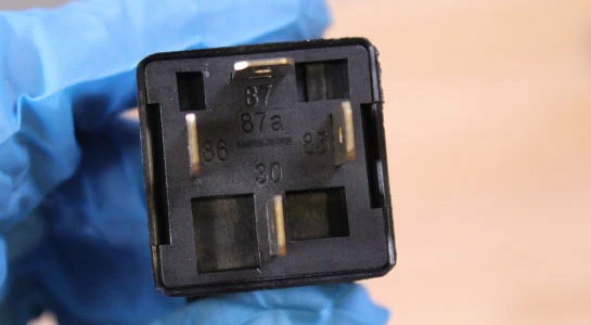
A relay consists of a coil, armature, and contacts. When voltage is applied, the coil generates a magnetic field that moves the armature, opening or closing the contacts. This simple mechanism allows small signals to control larger electrical loads efficiently. Understanding this principle is essential before performing resistance and continuity tests, as it helps identify where faults may occur within the relay structure. Relays are widely used in automation and protection systems due to their ability to isolate control and load circuits. This isolation enhances safety and efficiency, making relays a critical component in modern electrical engineering applications.
Tools and Preparation
Before starting the test, ensure the relay is disconnected from the power source to avoid electrical hazards. Set the multimeter to the appropriate resistance or continuity mode. Proper preparation ensures accurate readings and prevents damage to components.
- Inspect relay for visible damage or burnt marks.
- Keep multimeter probes clean and properly connected.
- Ensure correct mode selection before measurement.
- Work in a dry and safe environment.
Following these preparations ensures consistency in results and reduces the risk of measurement errors during the testing process. Practicing how to test relay with multimeter prevents faulty operations.
Step-by-Step Resistance and Continuity Test
To begin testing, place the multimeter probes on the relay coil terminals and measure resistance. A properly functioning coil will show a specific resistance range depending on its design. Next, check continuity across the switch contacts while activating the relay. Continuity should appear when the relay is energized and disappear when it is de-energized. This confirms that internal switching mechanisms are working correctly. Careful observation during each step is essential to avoid misinterpretation of readings. Even small deviations in resistance or continuity can provide valuable insight into relay condition and performance stability.
Interpreting Results
Interpreting the results of resistance and continuity tests helps determine relay health. Stable resistance within expected limits indicates a healthy coil. Lack of continuity where expected may signal worn or damaged contacts. Consistent irregular readings suggest internal faults that require replacement. Accurate interpretation ensures reliable electrical performance and reduces system downtime.
Conclusion
Using a multimeter to test relay resistance and continuity is a simple yet powerful diagnostic method. It helps quickly identify faulty components and ensures efficient system operation. Regular testing supports long-term reliability and prevents unexpected failures in electrical circuits, making it an essential skill for maintenance and troubleshooting tasks.